Disclaimer: I haven’t yet tested any of these projects as currently I haven’t got a possibility to print PCBs even using the toner transfer method. So use them at your own risk – as you should do with any other project on the Internet =)
From time to time I find cool PCB projects on the Web that are just too big for my use or otherwise unsuitable. Sometimes, those are proprietary and you cannot do anything about it. Other times, source files are available and I use my Eagle CAD knowledge and just minimize the PCB dimensions, replacing components and throwing out useless parts =) The power of open-source hardware, hell yeah. Anyway, here are three Eagle CAD projects that I’ve minimized and would like to share.
1) Tiny USB LIRC-compatible receiver
I was searching for a really tiny USB IR receiver for my laptop. I’ve been searching for a long time but it seemed that every solution wasn’t fitting and had one of three problems: 1) not tiny,2) not USB, 3) not for laptops. Finally, I’ve found a solution on this page that is also full of research on the topic… Still not small enough, but the page includes Eagle CAD files! So I’ve got them and opened them, and noticed that connectors could be replaced in favor of smaller ones. (USB-B for MiniUSB) I did that, rearranged the components on the board and it looked nice. That was the first version – the second has 4 holes for wire instead of connector, which makes it even smaller and embeddable – I plan to embed one in my laptop, one in my Raspberry Pi project and keep some assembled receivers in the drawer just for other projects =)
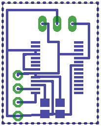
- First version – photo (some traces are interrupted but it’s OK – you have to use “Ratsnest” tool, so you get a nice ground fill polygon):

- Initial version – Eagle files are on the same page where I’ve found the circuit
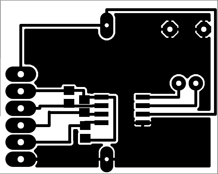
- Second version – photo (you can compare boards by looking at the FTDI IC):
- Second version – Eagle files
2) FTDI SIM card reader
This is a quite nice thing that Adafruit used to sell as kits for assembly. It included FTDI and RS232 interfacing circuit – I’d call the second part useless in our days, since nobody’d use COM port when there’s FTDI header available. I took the schematics, threw out everything that was related to RS232 and made the board as little as possible. Almost all the remaining components were replaced with their SMD variants, so this board now is as wide as SIM socket and just a little bit longer =) I guess I’ll order 5 PCBs of this after a while – just after I figure out why the heck I’d need them 😉 I’ll definitely have to extend the capabilities of the SIM card reading software that Adafruit provides (I guess it’s not actually made by them, but I’ll find the owner and fork his repository 😉 ).Also, I’ve made an eBay collection with needed parts in bulk, so that when time comes I can easily order everything – and so can everyone.
By the way, before making this board, I’ve assembled a deadbug-style prototype that actually is even smaller and works with USB-FTDI converter without any problems. Here’s a photo for you:
3) 12V-220V power inverter
This Arduino project by techmind.dk was featured at Hackaday some time ago and I got interested in it, having searched for something like that for a long time. It’s an inverter that takes 12VDC (or whatever here is) and converts it to the 220VAC. It’s controlled by AtMega 168P in DIP package, and there were no SMD components in the original circuit at all. I decided to fix that and asked the author about original .sch and .brd files – fortunately, he shared them. You know, many people just do not share their original files – and I guess that’s one of the biggest mistakes a person can make when designing something that wouldn’t be much of a problem to open-source. See, when all that’s
between a slightly useful project and quite useful project is uploading some files to a hosting, I prefer the latter.
Anyway, I opened those files, replaced through-hole components with SMD and rearranged the elements… I also needed to retrace the whole board, I’d say it was quite challenging =) I don’t know if it works as good as the previous version, though – haven’t tested yet, but you’d definitely need to change some pin assignments in firmware – I mean, LEDs and maybe something else I’ve forgot about, just compare the schematics and you’ll see – I’ll probably do this make a follow-up as soon as I’ll make this board myself. I think I’ll replace temperature sensor with DS18B20, but that’s just an idea.
I’ve already got more minimized projects that I’d like to tell you about, but I guess it will be later – after I check if they’re, in fact, working =)