Today, I’ll describe a temporary pinout for my prototype and some more technical details. Raspberry Pi seems to have a lot of useful pins. Still, it’s not enough of them for my goals. For now, I’m not including Arduino and thus I’ll need to suffice from what I currently have. There are some protocols RPi supports by hardware. Some of them, however, are supported only by software, and thus we need to use bit-banging and polling instead of hardware 1-Wire or infrared. This makes me sad and also loads the CPU, which I won’t have much of.
 The following pins are populated on a GPIO header every Raspberry Pi has. I’ve managed to find a usage for all of them. I’ve also noted which pins are connected to some kind of hardware inside the CPU that supports this protocol (like SPI/I2C/UART Raspberry Pi CPU has) and which pins will need to be controlled using bit-banging, emulating a protocol by software.
GPIO2 – SDA (HW)
GPIO3 – SCL (HW)
GPIO4 – 1-Wire (SW)
GPIO7 – CS1 (HW)
GPIO8 – CS0 (HW)
GPIO9 – MISO (HW)
GPIO10 – MOSI (HW)
GPIO11 – SCLK (HW)
GPIO14 – TXD (HW)
GPIO15 – RXD (HW)
GPIO17 – IR-out (SW)
GPIO18 – IR-in (SW)
GPIO22 – DRST (display reset) (SW)
GPIO23 – CSm0 (SW)
GPIO24 – CSm1 (SW)
GPIO25 – CSm2 (SW)
GPIO27 – DD/C (display D/C pin) (SW)
As we know, Rev. 2 boards have 4 more GPIO pins on a separate header, P5. This header also works as I2S connection point, so I think I’ll try to get some kind of cheap I2S audio chip supported by Linux and make a small audio breakout board – maybe 😉
GPIO28 – PCM_CLK (HW)
GPIO29 – PCM_FS (HW)
GPIO30 – PCM_DIN (HW)
GPIO31 – PCM_DOUT (HW)
There are some GPIOs that I certainly won’t be using in my project, and those aren’t available on some of the headers yet they control some of the RPi features and thus are tied to some resistors or separate connectors on RPi board, such as RPi audio output or I2C pins on RPi camera connector.
I’ll definitely re-use the following pins:
GPIO6 – LAN_RUN (resets USB hub, connected to pin 12 of SMSC chip)
GPIO40 – PWM-out (audio right channel)
GPIO45 – PWM-out (audio left channel)
I won’t need RPi audio anyway, as the quality is too shitty for me to consider this as an option.
Yet I plan on using RPi camera and I’d like to view activity LED sometimes, so the following pins will stay untouched:
GPIO5 – CAM_CLK
GPIO16 – ACT_LED
GPIO21 – CAM_GPIO
But those connectors certainly won’t be enough, so I’ll need to wait for the Arduino stage of my project =)
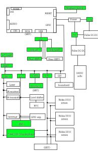
Current state of my project after this update
As I’ll make external “shields”, such as the Nokia 3310 screen shield, I’ll need some external connectors to attach things. I also need them to be waterproof, remember?
BTW, what about the displays? Each of Nokia 3310 displays has the following pins:
3V3
GND
RESET (needs to actually be used – we have to send a short pulse to initialise a display before usage, Philips even claims that not doing this can damage the controller)
MOSI (seems to perform the same function as SPI SCLK)
SCLK (seems to perform the same function as SPI SCLK)
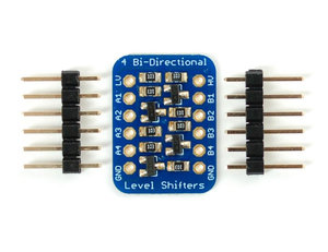
D/C (this is needed for the display to distinguish between data and commands being sent. Quite logical for the ease of display controller firmware developers, yet that’ll cause some problems as we will need to extend RPi’s hardware SPI by adding software extensions)
CS (seems to perform the same function as SPI CS, active logic level is low, too)
VOUT (needs to be tied to GND through a capacitor)
 As I’ve mentioned, I need CS multiplexer for the displays. Guess what – I’ve already built this, just haven’t had a possibility to check anything. I’ve used 74HC138 IC in SSOP case and a little board that extends SSOP to DIP, then desoldered DIP pins and attached the necessary wires. Raspberry Pi has two CS signals. I’ve decided that one of them will be a CS signal for enabling multiplexer, as it certainly won’t need to work for all the time. Multiplexer I use has 3 inputs and 8 outputs. Thus, I need 1 CS pin (as chip enable pin) and 3 GPIO pins to get 8 CS pins – and, as CS signal state doesn’t need to be changed that often during data transfer, I think I’ll be fine with this. I only will use 3 CS signals now but I guess I’ll occasionally find uses for those 5 left – like, for some of those small RF transmitters =)

Click on the image to see the whole picture, not just a part of it =) Active logic level is low because the same is for SPI CS signal.
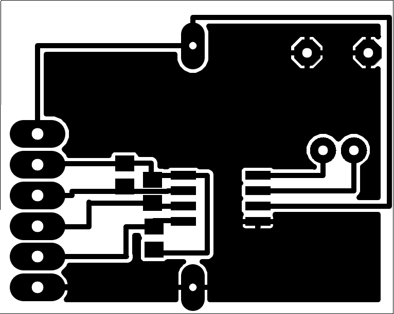
This is the pinout of display connector I already have made:
EXT_CON1 pinout:
3v3 GND RST D/C MOSI CLK CS3 CS2 CS1 CS0
I guess that looks scary. And I hope that’s waterproof enough.
But that’s not the only connector I’ll need. I’ll also need to connect more peripherals, like:
USB flash drives or Arduino through USB-UART connection… why not both, after all?
I2C keypad I’m planning to make
Infrared receiver and transmitter
External display that can be connected to TV-out of Pi.
DS18B20 sensors
SIM card readers
LED flashlight
Hardware interrupts – pins that are used to notify Pi that it’s about to receive/has to fetch some kind of important information that can’t wait, like a keypress from an external keyboard.
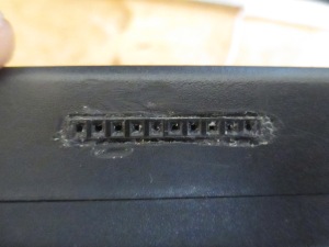
So – I managed to get one connector from hard disk drive. This was easy to reuse – though I needed a file and some more tools to minimise the connector so that it could fit in the case.
EXT_CON2 pinout:
SCL SDA 1W IRO IRI TXD RXD INT GND GND
DP1 DN1 VOUT VGND GND GND 3V3 5V VIN VIN

This connector will certainly require its own Eagle part =(
This all has been connected, too. Now I just need to think about external shields, and I guess LCD shield will be the first to be made =) Also, the mystery – how to fasten shields to the case? Screws might not be waterproof enough, magnets will have to be strong enough to hold everything and weak enough not to trigger the switches… I’ll have to think about it, for sure. I’m getting my LCDs during this week, hope they’re not buggy and will fit, else everything will be delayed.
For now, I just need to buy DC-DC converters. My search of custom one or two-layer PCBs for easily available DC-DC ICs kind of failed. I realised I have to go for pre-built modules =( I guess it’ll be hard to find one that won’t be bulky and will be efficient at the same time. So – VIN pins on the EXT_CON2 are not yet connected. Also, there’s just the same 5V-3,3V linear regulator =) I’ll certainly have to remove it, too – as soon as I get a pulse DC-DC.
Looks a little bit scary but it’s really so little that I couldn’t discard it.
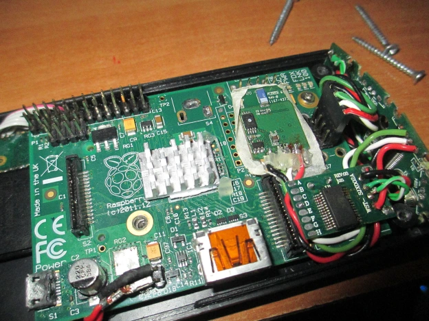
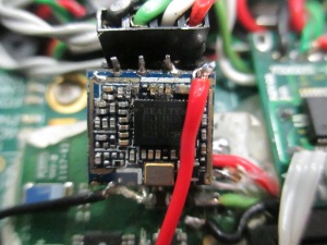
I’ve installed wireless module I’ve desoldered from a broken tablet PC I had lying around. Many of those, especially cheap Chinese craplets, have WiFi modules either soldered on the top of the board or connected by wires. This was the case for me, so this module was easy to get. Just one thing – some of USB devices that are soldered inside other electronics need 3V3 voltage, not 5V. So be careful with them, should you use one. As you can see, I also supply 3V3 to my module using a separate wire =)
My module is identified in lsusb as:
Bus 001 Device 005: ID 0bda:8179 Realtek Semiconductor Corp.
It’s based on RTL8188EUS chip, and Raspbian didn’t have drivers for it in the default distro. That’s when I understood this situation needs a lot of luck. I googled “how to set up network on raspberry pi model a”. See, I basically made a Model A RPi out of my RPi Model B. That means – no Ethernet. It turned out most people didn’t even think about this or even use network on a Model A. Those who did, used USB-WiFi adapter… And mine didn’t work because it didn’t have a driver.
As I obviously needed to install software, I needed network connectivity. One could have tried using PPPD, but it’s not in the default distribution and therefore doesn’t make sense – to set up PPP connection, I needed to install PPPD, and in order to install PPPD I needed network connection. PAN over Bluetooth had the same problem – no Bluetooth support by default =( So the only way to go was USB-WiFi module. Some modules are supported out of the box, but some require a firmware package to work. Downloading a firmware package from repositories has the exact same problem – you need network connection. One can always download a package .deb file, but if there are dependencies or version mismatch, you are screwed. Fortunately, my WiFi adapter didn’t need firmware packages, it only needed a driver, which happened not to have any dependencies =) For those curious where’d I get the
drivers – MrEngman on Raspberry Pi forums has compiled those drivers for Raspbian and published them, helping all those people that have WiFi adapter with the same chipset. Thank you very much, man! Should you arrive in Latvia – I owe you a beer 😉
And for those people that own RPi Model A and need a network connectivity for the initial setup – you have two ways. One is picking an out-of-the-box supported USB-WiFi from THIS LIST. Other is plugging your SD card into Raspberry Pi Model B, installing the packages using cable connection and plugging the card back. You’ve been warned 😉
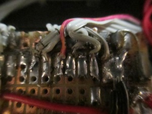
My shitty soldering job =(
I already think about making a more serious PCB. That is – I need to eliminate wiring and glueing modules using hot glue. Instead, all the modules I have have to be soldered to the board which’d hold everything. Also, I plan on using a separate USB hub chip – would be great if I could make a big protoboard both populating all the sockets, such as I2C, SPI etc, and holding USB hub and all the USB-connected modules – WiFi/BT/UART/whatever. I don’t really need separate boards, and if I remade this mess of wires I have now into a single shield board, it all would certainly be more stable and I’d certainly save some space in the case. So – now I just need to put all the components into Eagle CAD (my CAD of choice when it comes to electronics) and make a board… There is a problem, though. I wonder if I’d be able to do two-sided board by myself, as I can’t make vias now, and I’ll certainly need a lot of inter-layer connections. So – need to get to know how does one make vias at home =) I think about drilling small holes in the board where vias need to be, putting thin copper wires inside and soldering those wires to both sides of the board. Seems to be the way, at least.
With the custom board, I’ll certainly need one option: controlling modules’ power supply. That is – putting a transistor in the power line of each module, be it WiFi, screens or external modules. That will save energy and also improve reliability as it’ll be a possibility to turn off a module should it break and short-circuit everything or freeze everything. I can imagine some kind of power-on self-test-now. Let’s say there’s a startup program that checks all the modules, turning them on one by one. As there’s a possibility that a module is faulty and system will freeze, it has to be taken into account. When system freezes, RPi built-in watchdog will automatically reboot
the system. To avoid reboot loop, the program controlling modules will have to see which module failed on each startup and avoid turning it on again until the problem is solved. It could be done by making some kind of flag before launching module and removing it after the module has been sucessfully loaded, and checking for unremoved flags at each boot to determine whether the boot process had been interrupted due to a module failure. Or, maybe, making boot-up logs and parsing a log of previous boot during the boot process. Any way, this seems to be a good idea – I’ll just need hardware and software to support it 😉 Offtopic: it’s always as cruel as this. We might have excellent ideas – the only problem seems to be the implementation, that’s where most of the ideas get crushed.
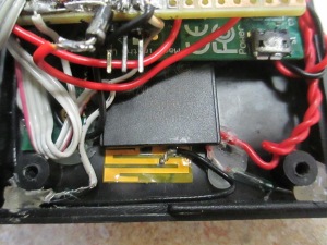
The card, with WiFi antenna and DS18B20 connector visible.
I’ve now bought 8GB SD card for my Pi, and it is still alive =) Seems to be indestructible no matter what I do. Now I just need to test whether the CS multiplexer is working or not, set up Bluetooth and WiFi AP software, install some necessary Python modules for the development, then connect one Nokia 3310 screen I already have and start testing. Software will certainly take its time. I can fit various modules into my setup but there’s no sense if I can’t really use them because there’s no program able to control them. God, this will be a challenge =) Now I see the following software problems for me to be solved:
- Nokia 3310 LCD control. I’ll need to see whether I’ll need to go for LCDProc or just build my own module on top of “spidev”, extending hardware SPI. That’ll be the challenge, especially when you remember that those LCDs will be the main output device for interacting with user.
- SPI multiplexer control. It will probably be simple yet problems are still possible.
- I2C keyboard driver. It’s a little bit early to talk about this because it hasn’t been designed yet, so there’ll be a separate article. But there certainly will be problems =(
- Menu controller. See, in my plans this keyboard will control some kind of menu where one’d be able to select various actions from those that will be available – and there’ll be a lot of actions available =) So this all needs to be coded somehow, and be reliable and fast.
- Infrared device control. It really depends on what I choose to do, I guess LIRC will do for the most use cases, but I’m still wondering – what if I’ll need more?
- Audio device control, that is – volume/active device/source/sink control. I’ll probably use Pulseaudio, but one needs to remember it’s far from perfect.
There’s a big possibility I’ve forgotten to include something, I know =) But you also know that I’ll tell you about the problems I meet on my way, sharing my experience with you. So you’ll se by yourself =)
Waiting for the board to be soldered on =)
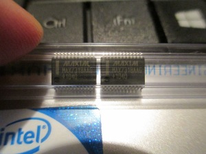
Talking about the I2C keyboard, I’ve received two I2C GPIO extender ICs from Maxim Integrated. They’ve been so generous as to provide me two free samples of it =) Now I’m thinking about how to design a I2C keyboard I’m planning to make. Won’t be that simple yet will be simple =) Gotta spend some hours in Eagle CAD preparing for this, I haven’t actually tried to make my own components in Eagle, so it seems that this will be the first one. I’ve already ran into some design difficulties. That is – my keyboard has to be CPU-efficient, generate interrupts only when a key is pressed, not require any CPU work unless there’s a pressed key (those are 3 different things 😉 ), and it also has to be reliable and cheap. However, I already do have some ideas in mind. I guess it’d be fun to ask advice about this project from Maxim technical support =) I guess they do have some good ideas about how to implement it, and will be able to provide the feedback about my implementation.
The next update will be when I’ll feel I have enough to say =) So stay tuned, it won’t be long. Just keep in mind that I also am preparing for the finals now, finishing my high school. That means I won’t be able to spend as much time on this project as I would be able, be it holidays =(